PC-350: Arduino Synthesiser
This project uses Arduino, a Nintendo DS touch-screen, a speaker, the Arduino Tone library and various other components to create a nicely packaged, stand-alone audio synthesiser. This page exists to hopefully aid people in creating something similar.
Contents
- PC-350: Arduino Synthesiser
Aim
To create a device that takes a users input and based upon that input play sounds. I want this ‘synthesiser’ to be simple to play, requiring little or no skill. Therefore, allowing the user to experiment with the sounds they are producing instantly as opposed to learning the technicalities of it first.
Research
Experimental Musical Instruments
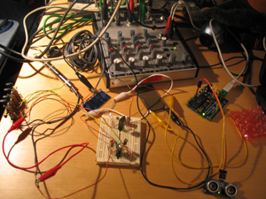
“The EMI project aims to create and experiment with more suitable instruments that will not be a boundary for the performers who do not have any traditional musical background. […] Nontraditional and computer based applications simulate the possibilities of creative freedom in music and enlarge this creative freedom into open form musical activities” - M.Koray Tahiroğlu, Experimental Musical Instruments
The Experimental Musical Instrument project in summary uses the Arduino and pureData to create musical instruments. The Arduino is used to measure physical activity through sensors, buttons, etc. pureData is used to generate the sound using the data collected by the Arduino. They say that some instruments last the test of time while others just disappear and that Experimental Musical Instruments can too last the test of time; even if these instruments are free of the traditional tonal structure and interface of other instruments. This freedom of use and sound could even lead to more creativity.
The Experimental Musical Instruments should be powerful enough for the performer to really enjoy playing the instrument. This can mean that the interface can be very simple but pureData takes that input and turns it into a very powerful sound. This response from the instruments leads to the user enjoying the results and therefore wanting to explore everything they can do on the instrument.
I want to create sound straight from the Arduino rather than use pureData or Max/MSP. The reason for this is because I want the device to be standalone and not require a computer to run. This makes the device more physical instead of having the computers existing hardware generate the sounds. This is my preference, however, and I expect the sounds produced using pureData are of high quality. I like their philosophy that lies behind the instruments that allows anyone to play instruments and produce interesting sounds easily. This creates more performers and doesn’t alienate people like traditional instruments might.
Interfaces
Arduino and Nintendo Wii Nunchuck
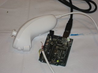
This is a tutorial explaining how to get the X and Y axis values and the X, Y and Z accelerometer values from a Nintendo Wii Nunchuck into the Arduino. I like the idea of using the motion of the arm as an input for the device and the implementation is very simple. There is even an adaptor that allows you to use the nunchuck without any modifications to it. The nunchuck costs £10 to £15.
Arduino and Nintendo DS Touchscreen
I found a very thorough tutorial written by ‘kousaku’ explaining how to connect a Nintendo DS touchscreen to the Arduino and read the X and Y values of the touch. It also explains how touchscreens work. This version of the tutorial (link) is a translation of it into English. However, the original version has clearer diagrams and photographs.
I prefer the idea of a touchscreen as opposed to a nunchuck because there are only the X and Y values to compute and a screen is a more familiar interface for users. In addition, I have found many resources explaining how to get it to work correctly and an existing project that uses the technology.
Sound Out
The Arduino cannot play high quality sounds straight ‘out the box’. There are several methods of producing sound from the Arduino:
- Bit-Banging This sends an electrical signal straight to the speaker pin, it generates square tones that are very harsh.
- Hardware PWM uses timers and PWM to create reasonable quality audio (could be used for playing recorded sounds).
- R2R/Hardware DAC uses resistors or a chip. It creates high quality waveforms (and audio).
- Voltage Controlled Oscillators uses PWM to control oscillators that play sounds, it produces nice smooth waveforms.
- MP3 Decoder Chip this is a chip that reads and plays mp3s.
- Controlling a computer this is using the arduino as the sensor and sending the data to the computer and have the computer do the hard work of sound generation (using pureData/MaxMSP for example). This method is used in the Experimental Musical Instruments mentioned above.
- Physically play an instrument using motors/servos to play keys on a piano or hit a cymbal.
These methods are listed in the article ‘Arduino Sound’ at uchobby.com. You can find part one here , part two here and part three here.
FreqOut from the Arduino playground is a simple implementation of a tone library. It defines notes as frequencies and allows them to be played through a speaker. In order to play tones on the Arduino, you need to use timers to space out the notes. Otherwise you end up with lots of notes being played at once.
This tutorial explains how to create a very simple synthesiser using an LDR, a speaker and the Arduino Tone library. The Arduino tone library looks very useful and makes it incredibly simple to produce tone using the Arduino. All you need to do is plug in the speaker to a pin on the arduino with a resistor and then use tone1.play(NOTE_A4); to play that note.
User Scenario
These are some examples of the types of people that may use my device:
- Someone who is curious about what the device does. This type of person will see the device and possibly ask to try it out. They could be any age or type of person as long as they are curious enough to act on their thoughts.
- A musician or performer could use the device in a live performance. This type of person will be limited to people who like performing. The age of the person could be any age but I would imagine it would be between 18 and 30.
- A musician could use the device in a song or recording. The type of person that would do this would be an experimental musician due to the fact that the device is not a traditional musical instrument. The age group could be any age but as before, I imagine it would be around 18 - 30.
- An Arduino enthusiast might enjoy using the device because they are interested in Arduino and want to see it working and how it works. This person could be any age but would have to be an Arduino user.
Development
I have decided to use a Nintendo DS touchscreen as the main interface for the device. I could use any touchscreen with a four-wire set up but I have decided to use the Nintendo DS screen due to its size (3 inches). I want to use the Arduino Tone library to generate the sounds based on the position of touch on the touchscreen. I also want to include a volume control and a headphone jack in the device for increased functionality.
Requirements & Analysis
Components
- Nintendo DS touchscreen (Link)
- Potentiometer for volume control (Link)
- Headphone jack (Link)
- Speaker (Link)
- Solder and Solering Iron
- Arduino, Breadboard, Wires and USB cable
What I Need to Do
- Connect the speaker to the Arduino and control it programmatically
- Connect the touchscreen to the Arduino and get the readings from it to the Arduino
- Connect the volume control and headphone jack
- Fine tune the program to get the best sounding results
The program
This is pseudo code explaining how I think the program powering the device will work:
Load the Arduino tone library

Set up touchscreen and speaker pins

If touchscreen is pressed:

	Take touchscreen X and Y and play a tone on the speaker using the tone library
Design & Implementation
The speaker
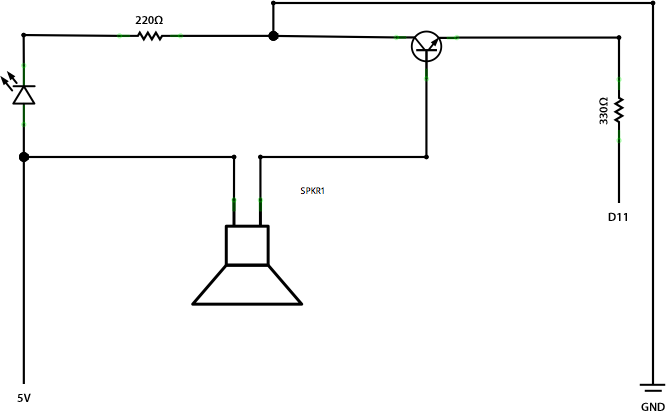
Firstly, I got the speaker working with the Arduino. To do this I used a PNP general purpose amplifier in order to boost the signal loud enough for the speaker I was using. It was a fairly simple circuit and I followed my previous tasks to figure out how to wire it up correctly. Below are the schematic and breadboard of the Arduino:
Breadboard
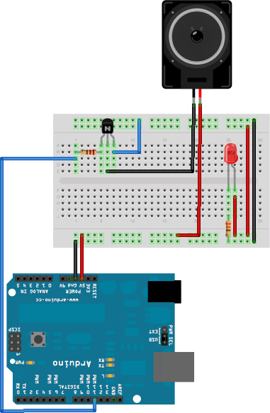
Schematic
To test the speaker is working correctly, I found a program in the Arduino playground called PCMAudio which plays back a very small sound clip (the Mac start-up sound). I made sure all the pins were correctly defined in the code and uploaded it to my Arduino and all worked fine.
Next I decided to look at how I could generate sound from the Arduino by sending signals straight to the speaker pin. I wrote a simple program that sends 0 - 255 to the speaker with a delay of 100ms between each send. This produces a tone output that rises in pitch. I also implemented a random tone function that sends a random value between 0 and 255 to the speaker with a delay of 500ms between each send. This produces a blippy jumpy sound of random beeps. Finally I removed the delay of 500ms to experiment with the results and found that this produces static from the speaker like on a radio or TV. A link to my code is below, please note that only one of ‘Tone’, ‘Random tones’ or ‘Static’ can run at once.
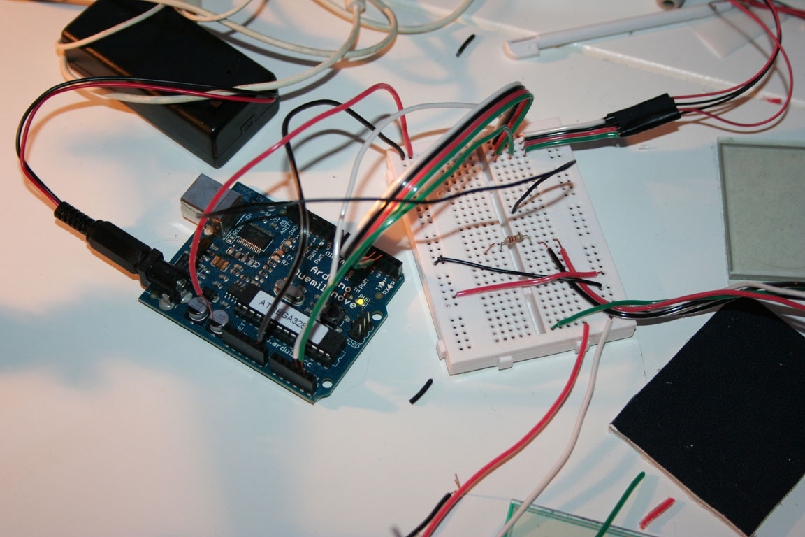
The touchscreen
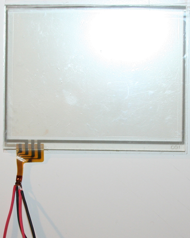
I purchased 2 DS touchscreens from eBay along with some P6 connectors. The P6 connectors hold the ribbon cable that comes out of the touchscreen, this tutorial recommended that I bought the connector. However, I found that the connectors were far too small to solder wires on to, the wires I had were at least double the connectors size. Instead of using the connectors I decided to solder the wires straight onto the ribbon. To do this I had to cut the ribbon connector into four sections and then attach a wire to each of the four sections.
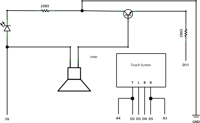
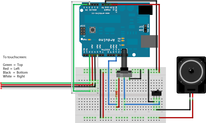
The four wires on the touch screen correspond to the Top, Left, Bottom and Right of the screen (from left to right). Using this image as a reference, I wired up the touch screen to the Arduino. I kept my set up from before with the speaker, so the touch screen went onto that. The four wires of the screen need to go to four digital pins so they can be turned on and off. In addition to this, the Top and Right wires need to also go to two analog pins so their readings can be read. Below is the schematic and breadboard setup:
Breadboard
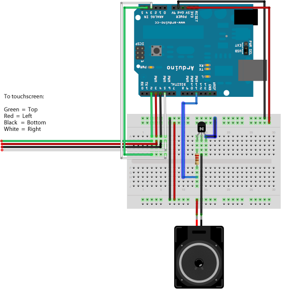
Schematic
To test that the touchscreen was working correctly, I modified the code found here. I stripped out anything I didn’t need like the functions to light up LEDs.
View the modified touchscreen code
This code worked as expected. However, something I modified after testing the screen was line 89 which read:
if(touchX < 1000 and touchX > 0 and touchY < 1000 and touchY > 0)
I changed the values from 1000 and 1000 to 600 and 630. Without this change, the touchscreen gave readings even when it wasn’t being touched. I think the reason I had to change the values is because there are lots of different manufacturers of DS touchscreens and they all have different calibrations.
The touch screen worked correctly and gave values for the X and Y positions of touches on the screen. This file is an output from the Arduino Serial Monitor showing the results. When I touched the screen, numbers would appear in the monitor and when I stopped touching it, they would stop. The values are in a small range so I will have to do some processing of them before using them in the final device.
Putting it all together
Now all that needs to be added to the circuit is the volume controller and the headphone jack. The volume controller is just a potentiometer which I have used before in my tasks so I can use them as a reference. The headphone jack was a bit more confusing because I couldn’t find a datasheet for it. I found an article on TRS Connectors which explained how the jack works. I wanted to have the speaker turn off when the headphone jack is plugged in and this article explained that it works like a switch, when the headphone jack is plugged in, the switch turns off the speaker.
I soldered the parts and worked out that the headphone jack has one side that needs to go to ground, one side that goes to the speaker and then the middle that goes to to the volume control (which in turn goes to the Arduino pin which controls the sound).
Below is the breadboard and schematic of my final set up (click them to view full size versions):
Breadboard
Schematic
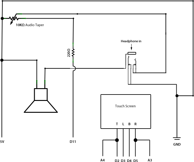
Note: Fritzing does not have a TRS connector built in to it, so I have used a switch with similar connectors. The schematic, however, shows the set up more clearly.
The code I am going to use is a modified version of my touchscreen code mentioned earlier. I need to add in the code to load the Arduino Tone library and then play a note depending on the X and Y touch values.
The code is fully commented but to summarise; it loads the Arduino tone library, defines the DS screen pins and the speaker pin. In the setup function, the tone library is started on the speaker pin. In the loop function, it checks if the DS screen is being touched (by checking the touched function). If the screen is touched, the X value is mapped between 0 and 500 for the tone and the Y value is mapped between 0 and 1000 for the length of the note. Every time the screen is touched, the minimum and maximum values that have been touched, X or Y, are stored in order to complete the mapping. These mapped values are then used to output a tone and a length of tone.
In the touched function, the X and Y values are read from the screen. If the values aren’t in the right range, then the function returns false.
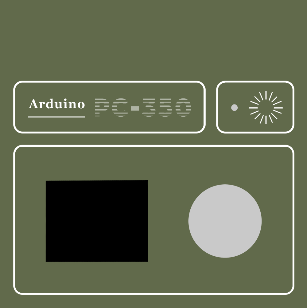
Finishing off
I want the device to somewhat resemble a synthesiser. My first attempt was far too small (link). For my second attempt, I took a cardboard box and measured it. I then measured the speaker and touchscreen. Using these measurements I created an accurate template that could hold a speaker, screen, volume control and headphone jack. The design is to the right.
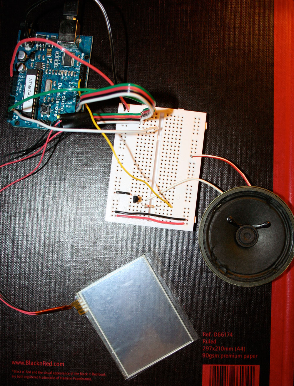
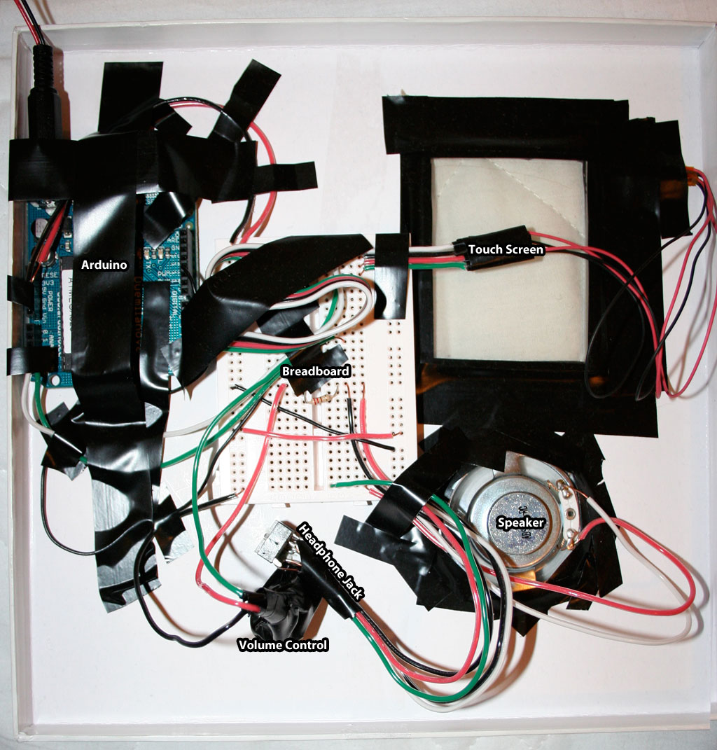
I then cut out holes for each component and fitted them into the spaces. I used lots of electrical tape to hold everything in place. Below is a photo of the Arduino, breadboard, wires and components all in place and labeled at the back of the box:
Testing
To test the device, I experimented with different ranges of pitches that are sent to the speaker. On line 63:
inputValX = map(touchX, minX, maxX, 100, 500);
I tweaked the values 100 and 500 to see what different results I would get. These seemed to be the best. I found that setting the minimum value to 0 led to very low frequencies that didn’t really go with the higher frequencies. The maximum pitch can be 1000 but I found that was far too harsh and uncomfortable to listen to. On line 64:
inputValY = map(touchY, minY, maxY, 0, 1000);
This changes the length of the note. I found that 1000 (ms) gave the best results. The lower the number, the faster the notes and the less smooth it sounds.
I tested the volume of the device by turning it up and down. I found that at the beginning of turning the knob, there is little increase in volume up until about half way through turning the knob when the volume increases quickly.
Finally, I tested the touchscreen for its response to touch. I touched the bottom left of the screen and low notes were played. I touched the top of the screen and high notes were played. I moved my touch around the screen randomly and the notes that are played are responsive to the direction and speed of touch.
Final Outcome
I am pleased with the final outcome of my project. It does what I set out to achieve, I find it fun to play; I have spent a long time playing on it. I am happy with the Tone library and the sounds it produces straight from the Arduino. When researching about methods of producing sound from the Arduino, I was worried that I wouldn’t be able to get high quality sound without some sort of shield which I didn’t want.
One problem I have with the device is that when you are touching the screen, the sounds play fine. However, when you remove your finger from the screen, a high pitch note is played at the end. I think this is due to the touchscreen catching up with the fact you have removed your finger and therefore playing a high note that you didn’t necessarily intend to play. I find it annoying that it is always played when you remove your finger, but it is not detrimental to the playback of the device.
Something that I would have liked to investigate further would have been to use PWM and oscillators to generate sine waves. Sine waves are often a basis to sythesisers and I think I could have got some good results by using these in combination with a touch screen. The reason I didn’t use them was because I found out about them late into the development of the project and I had already purchased all the parts I needed.
Demos & Final Code
This is a sound recording of the device being played (from the headphone jack).
Note: Turn the volume right down before playing this! It can be very loud.
Finally, this is the code running on the device; you can find the schematics and breadboard of the system above.
References
- Experimental Musical Instruments http://mlab.taik.fi/~korayt/emipro.html
- Call for EMIs http://ultranoise.es/blog/?p=133
- Wii Nunchuck tutorial http://www.windmeadow.com/node/42
- Wii Nunchuck adaptor http://www.freeduino.eu/index.php?main_page=product_info&cPath=3&products_id=6
- DS Touchscreen tutorial http://translate.google.co.uk/translate?u=http://kousaku-kousaku.blogspot.com/2008/08/arduino_24.html&sl=ja&tl=en&hl=&ie=UTF-8
- DS Touchscreen tutorial (translated and reformatted) http://kalshagar.wikispaces.com/Arduino+and+a+Nintendo+DS+touch+screen
- Arduino and touchscreen documentation http://mnicolato.altervista.org/arduino/ardtouch.htm
- Arduino and DS touchscreen RGB mixer image http://www.flickr.com/photos/mowcius/3572919432/
- Arduino and DS touchscreen RGB mixer code http://www.arduino.cc/cgi-bin/yabb2/YaBB.pl?num=1243499684/2#2
- Arduino Sound, Pt. 1 http://www.uchobby.com/index.php/2007/11/11/arduino-sound-part-1/
- Arduino Sound, Pt. 2 http://www.uchobby.com/index.php/2007/11/22/arduino-sound-part-3-playing-a-melody/
- Arduino Sound, Pt. 3 http://www.uchobby.com/index.php/2007/11/14/arduino-sound-part-2-hello-world/
- FreqOut at the Arduino Playground http://www.arduino.cc/playground/Main/Freqout
- ToneOut ITP tutorial http://itp.nyu.edu/physcomp/Labs/ToneOutput
- Arduino Tone Library http://code.google.com/p/arduino-tone/
- PNP General Purpose Amplifier data sheet http://www.fairchildsemi.com/ds/2N%2F2N3906.pdf
- PCMAudio at the Arduino Playground http://www.arduino.cc/playground/Code/PCMAudio
- Mac Startup Sound http://musicthing.blogspot.com/2005/05/tiny-music-makers-pt-4-mac-startup.html
- TRS (Headphone jack) schematic symbol http://en.wikipedia.org/wiki/TRS_connector#Configurations_and_schematic_symbols
- Lady Ada’s WaveShield http://www.ladyada.net/make/waveshield/
Notes
- Image taken from http://mlab.taik.fi/~korayt/emipro.html and belongs to the original owner.
- Image taken from http://www.windmeadow.com/node/42 and belongs to the original owner.
This project by Max Novakovic is licensed under a Creative Commons Attribution-ShareAlike 2.0 UK: England & Wales License.